Evaluation of a Hand-held GPR MD sensor
system (ALIS)
Motoyuki SATOa*, Jun FUJIWARA b , Xuan FENGa , Zheng-Shu ZHOU a and Takao KOBAYASHIa
a
b Tokyo Gas Co. Ltd., Arakawa-ku,
Abstract
ALIS (Advanced Landmine Imaging System),
which is a novel landmine detection sensor system combined with a metal
detector and GPR, was developed. This is a hand-held equipment, which has a
sensor position tracking system, and can visualize the sensor output in real
time on a head-mounted PC display. In
order to achieve the sensor tracking system, ALIS needs only one CCD camera
attached on the sensor handle. The new hand-held system ALIS is a very compact
and do not require any additional sensor for sensor position tracking. The acquired
signal from the metal detector and GPR is displayed on the PC display on real
time, and the sensor trace can be checked by the operator. At the same time,
the operator can visually recognize the signal on the same display. The CCD
captured image is superimposed with the GPR and metal detector signal,
therefore the detection and identification of buried targets is quite easy and reliable.
Field evaluation test of ALIS was conducted in
Keywords: GPR, Metal detector, Hand-held, Sensor tracking, Landmine detection
1. INTRODUCTION
Humanitarian Demining is gathering interest all over the world. Detection of antipersonnel (AP) landmines, whose casing are made of plastic, is the principle task of humanitarian demining. Even in a plastic AP-landmine, normally very small metallic part is included, and it can be detected by a metal detector (MD). Therefore, MD is widely used for humanitarian demining operation. However, the problem of MD is its very high false alarm rate. Ground Penetrating Radar (GPR) is a useful sensor for detection of buried antipersonnel landmines, and we think it can be used for identification of AP-landmines, if it is used together with MD.
The combination of GPR and MD has been
employed in some landmine detection systems. However, the method of combining
two sensors must still be developed. We have introduced a novel technique of
tracking the sensor position into a combined MD and GPR sensors, in order to
use it as a hand-held system. This is Advanced Landmine Imaging System (ALIS)
sensor system, which was developed under the grant of
The Japanese government has carried out
efforts for rehabilitation of
For the purpose of contributing to the
execution of the Project by the Transitional Administration of Afghanistan, the
Government of Japan extended a grant to the Transitional Administration of
Afghanistan in accordance with the Exchange of Notes signed on
2. ALIS SYSTEM
2.1
ALIS configuration and operation
ALIS is a hand-held landmine detection
sensor, which is equipped with a metal detector and GPR. In addition, it can
track the sensor position while scanning by a deminer in real time. The sensor
signals from the metal detector and GPR are stored in a PC together with the
sensor position information. All the system is controlled by the PC, which is
inside a daypack on the back of a deminer. WINDOWS based software controls the
system, and the operation can be done directly by the PC, but usually we use a
handheld PC display which is connected to the PC via wireless LAN. The deminer
usually monitors the metal detector signal displayed on a head-up display.
Fig.1 shows the ALIS system under operation. A deminer is scanning the handheld ALIS sensor, and hanging a daypack which contains the operating PC. The deminer is also wearing a head-up display. The same display that the deminer is monitoring is transmitted to a handheld PC display, and several operators can monitor the operation. Fig.2 shows the ALIS hardware. For the usual operation of ALIS, we need one operator who scans the sensor, and another operator who controls and monitors the sensor signal.

 The scanning by ALIS follows
the exactly same procedure that normal hand-held metal detector is using. A
deminer stands in front of the boundary of a safe zone, and scan the area about
1m by 1m using the hand-held sensor. We recommend scanning continuously, even
the deminer detect anomalous signal from the metal detector. After scanning the
area, we process the acquired data sets using the same PC. Normally, the
processing requires one to a few minutes until all the data sets are displayed.
Finally ALIS provides a horizontal visualized image of the metal detector
signal, and 3-D GPR information. The information of 3-D GPR is usually too much
for interpretation on the site, so ALIS displays horizontal slices (C-scan) of
the GPR signal. An operator can move the depth of GPR slice images, and can
detect the buried landmine image.
Another unique feature of ALIS is its compatibility to the conventional landmine detection operation. Landmine detection by metal detectors are quite common demining operation in many courtiers. The procedure of the demining is well established, and many deminers have been trained and they are exactly following the procedure to avoid any accident. Any new sensor for landmine detection requires a change of the procedure of operation. However, ALIS requires minimum modification of the procedure, as we have described. The ALIS is a add-on system which can be attached to an existing commercial metal detector. The performance of the metal detector does not change by adding ALIS system. The operator still hears the audio tone signal from the metal detector, and can detect anomalies using their own experience. ALIS adds visualized image of metal detector sensor, and GPR images. Therefore, the operator can obtain additional valuable information, although the operation of the sensor does not have to be so much changed.
2.2
Sensor tracking system
A conventional MD sensor outputs audio signal and an operator has to estimate the position of the buried objects only from the sound. If the sensor signal can be visualized, detection of objects can be much easier. Visualization of the sensor is possible, if we can obtain the sensor position together with the sensor signal. However, most of the conventional hand-held sensor could not provide the sensor position. In order to obtain the senor position, we can use a stereo-vision system, which needs at least two camera set around the sensing position. Sensors mounted on a robotic arm can track the sensor position, but the size of the senor becomes larger and is not suitable for a hand-held sensor.
In order to solve these problems, we developed a sensor tracking system by using a CCD camera mounted on the sensor itself and attached it o the MD and GPR sensors. In Fig.2, two white disks placed near the scanning area are standard positions of the sensor tracking system, and its position is traced in the CCD captured image. Compared to the location of the plastic discs, the sensor position can be tracked in real time. The output signals of MD and GPR are stored in a PC together with the sensor position information. The MD signal is visualized on the CCD captured image and they are projected on a head-mounted PC display of the operator. Three types of information, i.e., CCD image, GPR and metal detector are continuously acquired. However, due to the time required for data acquisition, the sampling data interval is several points per second. Fig.3 shows an example of the trace of the sensor head scanned manually. Each dot indicates the points where the data was acquired. We can find that the data acquisition points are quite random. Fig.4 shows the visualized metal detector signal superimposed on the CCD image.
2.3
GPR
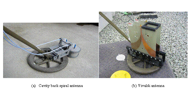 ALIS uses an impulse GPR
system which operates at the frequency range of 1GHz-3GHz. Two orthogonal
polarization cavity back spiral antennas are used, and they are mounted in from
of the MD coil as shown in Fig.5(a). This system uses an impulse radar system.
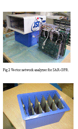
We are also developing a stepped frequency GPR system, which uses a Vivalidi-type
antenna as shown in Fig.5(b)[1]. This type of antenna will be used combined
with a compact vector network analyzer. The system is now under evaluation. Interferences
between MD and GPR can be minimized by sensor calibration.
2.4 Metal
detector
We use a commercial metal detector (CEIA MIL-D1) for ALIS system. More than 200 sets of this type of metal detector have been operated, and we believe it is one of the most reliable sensors, for landmine detection in Afghan soil condition. The interference of the two sensors, namely GPR and metal detector has been studies. MIL-D1 has a calibration function, and even metal objects are located near the metal detector sensor, the output signal can be compensated by this calibration procedure. We found that, if the antenna is firmly fixed against the metal detector sensor position, the influence of the existence of GPR antennas can be completely canceled. And the sensitivity of the metal detector to buried objects does not change. However, the influence of the metal detector sensor to the GPR signal is hard to compensate. Therefore, the GPR antennas are mounted in front of the metal detector sensor.
2.5 Data processing and display
The GPR data acquired with the sensor
position information is processed after the scanning the ALIS sensor over the
area of about 1m by 1m. At first, all the acquired data set was relocated on a
regular grid points. Interpolation algorithm is used for this process. After
the relocation of the data sets, metal detector signal can directly be
displayed in a horizontal image as shown in Fig.6(a).
3-D GPR image is reconstructed by Kirchhoff
migration algorithm. The Kirchhoff migration gives the output wave field ![]() at a subsurface
scatter point
at a subsurface
scatter point ![]() from the input
wave field
from the input
wave field ![]() , which is measured at the surface (z=0). The integral
solution used in migration is given by:
, which is measured at the surface (z=0). The integral
solution used in migration is given by:

![]()
![]() (4)
(4)
 where
where ![]() is the RMS velocity at
the scatter point
is the RMS velocity at
the scatter point ![]() and
and ![]() , which is the distance between the input point
, which is the distance between the input point ![]() and scatter point
and scatter point ![]() .
. ![]() is obliquity factor or
directivity factor, which describes the angle dependence of amplitudes and is
given by the cosine of the angle between the direction of propagation and the
vertical axis z.
is obliquity factor or
directivity factor, which describes the angle dependence of amplitudes and is
given by the cosine of the angle between the direction of propagation and the
vertical axis z. ![]() is the spherical
spreading factor. The time derivative of the measured wave field yields the
90-degree phase shift and adjustment of the amplitude spectrum. In this signal
processing, the vertical inhomogeneity of the soil is considered.
is the spherical
spreading factor. The time derivative of the measured wave field yields the
90-degree phase shift and adjustment of the amplitude spectrum. In this signal
processing, the vertical inhomogeneity of the soil is considered.
The migrated GPR data gives 3-D
reconstructed subsurface image. However, we normally use only horizontal slice
image (C-scan) as shown in Fig.6(b) for data interpretation. This is due to too
much clutter in 3-D image and from many trials, detection of buried landmine
image in the horizontal slice is most reliable.
Data acquisition takes about several minutes, which is almost equivalent to the time required for normal scanning operation of a conventional MD, and the signal processing needs about two minutes after the data acquisition. Wireless LAN sends sensor data to a handheld PC display for judging the image by multiple operators.
2.6 Detection
of landmine
After all the data processing was finished,
we use the metal detector and GPR signals for detection of buried landmine.
Currently, we are interpreting the data manually. At first, we find anomaly appears
in the metal detector image. Normally, it is quite obvious, but it includes
many signals due to metal fragments and other objects. After marking the
location of these anomalous points, we observe the GPR image. We move the depth
of the horizontal slice images and try to find a continuous image, which can be
a GPR image of buried landmines.
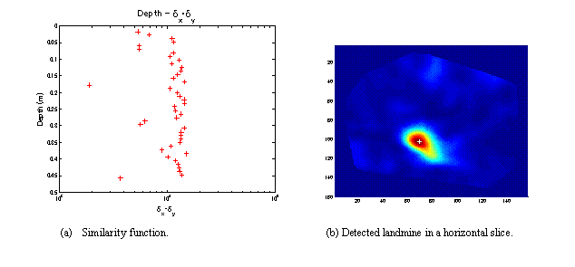
This detection algorithm was now implemented in a semi-automatic software. In this algorithm, we calculate the similarity between the adjusting two horizontal slices and detect the location of buried land mine. Fig.7 shows an example of the output of the buried land mine detection algorithm, and in Fig.7(a) we can find the indicator shows the minimum at 0.17m in depth, and corresponding horizontal GPR slice image shown in Fig.7(b) shows the location of the detected buried landmine.
3. Evaluation test in
After laboratory tests, we have conducted
field evaluation test of ALIS in
At the CDS site, we could validate the operation of the ALIS for known targets in various conditions. The climate when we conducted the field tests was partly rainy, and water content of the soil at CDS site was about 10% , correspond to the dielectric constant of 5.3. Real PMN-2 and Type 72 landmines without booster were buried at the CDS site at different depths between 0 and 20cm, and we could find that the metal detector can detect landmines buried shallower than 15cm, and GPR can show clear images of landmines, which are buried up to 20cm in depth. We also found that the metal fragments, which are included in the soil does dot show clear GPR image, therefore we could discriminate metal fragments from landmines by ALIS.
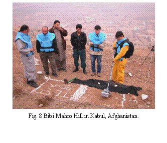
Bibi Mahro Hill is a real landmine field, and we buried a PMN-2 plastic shell model filled with TNT explosive and put a small metal pin in it imitating the metallic part of a booster of the real landmine. In addition, we buried a small metal fragment about 15cm apart from the landmine model. Fig.9 shows the ALIS visualization output at Bibi Mahro Hill. Fig.9(a) is the MD image, and we can find two separated metal objects in the figure. CEIA MIL-D1 has a differential signal output, and a single metal object shows symmetric response, having a null point at the center. Fig.9(b) shows the GPR image, and we can find only one clear image, which correspond to the landmine model. Note that the center of the two sensors differs by 20cm, then the images in Fig4 has 20cm offset.
4. BUGGY MOUNTED SYSTEM
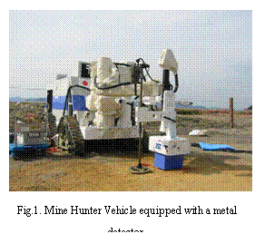
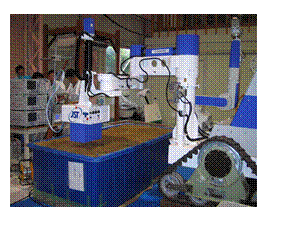
A remote metal detection buggy system can
range over a large area, and improves work efficiency based on conventional
metal detection. The robot arm uses
conventional metal detection technology
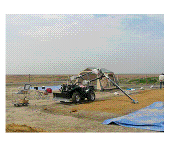
that allows users to remotely confirm the presence of mines. ALIS was equipped on a robot of a buggy system
developed by the group of Prof. Hirose at
Fig.10 shows
on example of ALIS GPR image acquired by a buggy mounted system.
5. CONCLUSIONS
|
We developed ALIS, which has high efficiency
with better reliability for landmine detection by MD-GPR sensor fusion. The
developed ALIS can visualize the signal, although it is a hand-held sensor.
ALIS was evaluated in real mine field in
Acknowledgements
Part of this work was supported by JSPS
Grant-in-Aid for Scientific Research (S)14102024 and
by
References:
[1]
M.Sato, Y.Hamada, X. Feng,
F.Kong,Z.Zeng, G. Fang,”GPR using an array antenna for landmine detection,”
Near Surface Geophysics, 2, pp3-9,2004.
[2]
X. Feng and M. Sato, “Pre-stack migration applied to GPR for
landmine detection,” Inverse problems, 20, pp1-17, 2004.
[3]
X. Feng,, J. Fujiwara , Z.
[4]
X. Feng,, Z.
[5]
http://www.jst.go.jp/kisoken/jirai/EN/index-e.html